Frame Hardware Manual
Here you’ll find all the details about how Frame works under the hood. For software related information, be sure to also check out the Frame SDK including Lua API pages.
Key features
- 640x400 color OLED display
- 20° FOV optic
- Optional personalized prescriptions
- Thin and light 6mm lenses (not including optional prescription)
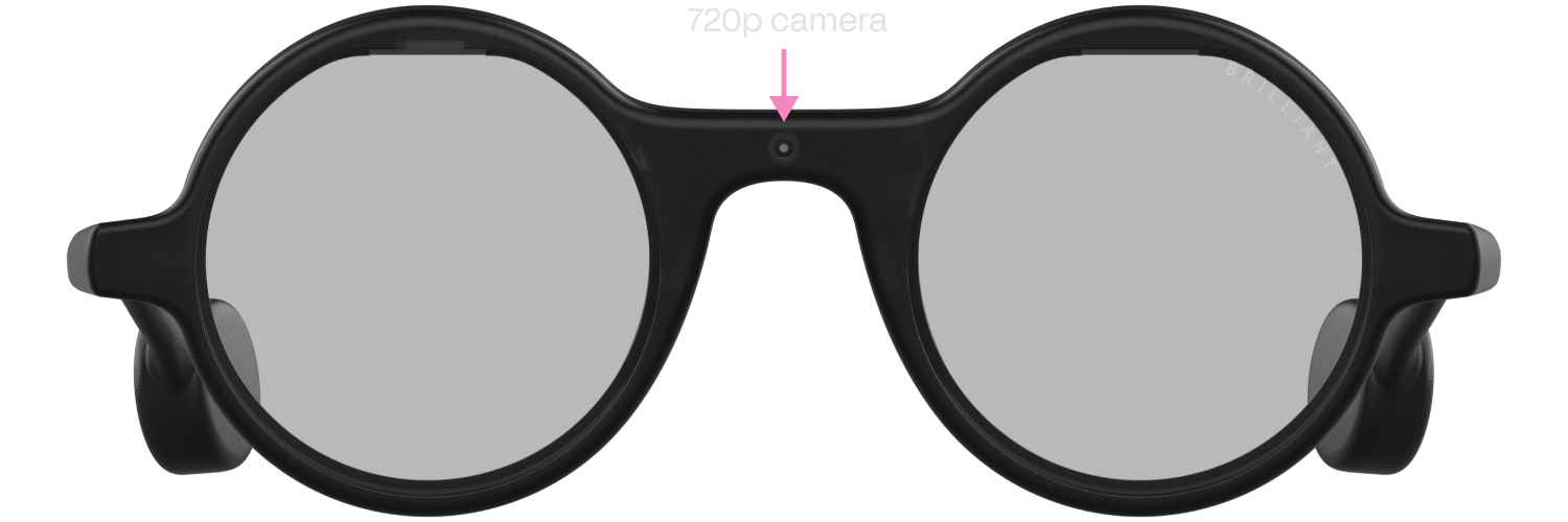
- 720p low power color camera
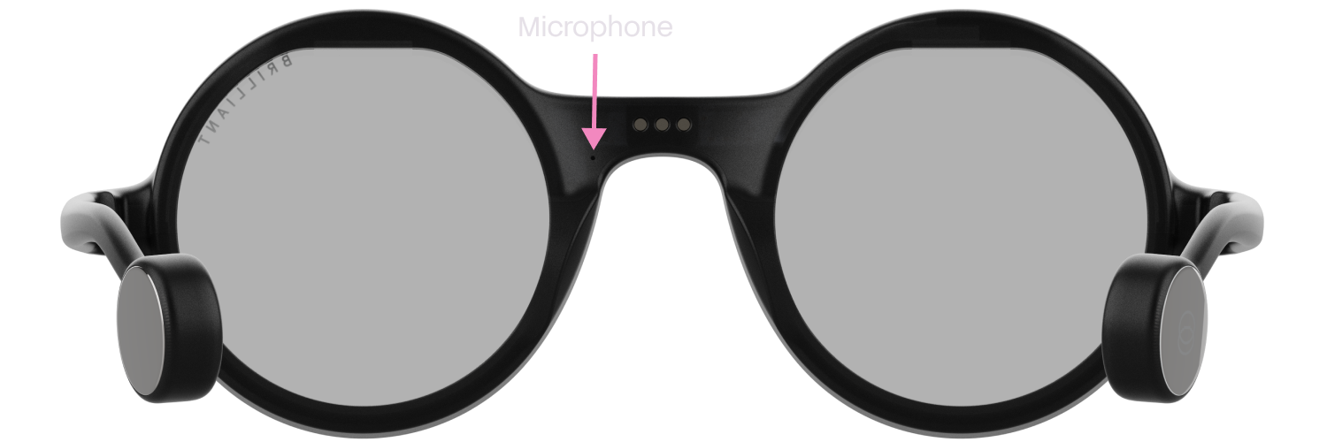
- Microphone
- FPGA acceleration for graphics and imaging
- Bluetooth 5.3
- 210mAh built-in rechargeable li-ion battery
- 3 axis accelerometer with tap detection
- 3 axis e-compass
- Full featured Lua based OS
- Charging dock with USB Type-C & 140mAh battery
Example uses:
- Generative AI on the go
- ML based image augmentation
- Computer vision research
- QR code & barcode detection
- Heads up telemetry
- AR app & game design
Contents
- Hardware block diagram
- Bluetooth MCU
- FPGA
- Display
- Camera
- Microphone
- Motion Sensor (IMU)
- Power
- Charging cradle (Mister Power)
- Schematics
- Mechanical
- Device characteristics
- Safety & limitation of liability
Hardware block diagram
This diagram shows a general overview of the Frame internal hardware architecture.

Bluetooth MCU
the Bluetooth MCU serves as the main processor for Frame. It handles all network communication and running of user logic. The MCU used is the nRF52840 from Nordic. It contains a 32bit ARM Cortex-M4F CPU running at 64MHz, 1 MB of flash storage, 256 KB of RAM, and features Bluetooth 5.3 connectivity.
As standard, Frame comes with a feature rich Lua based OS that allows for scripting and remote access fully over Bluetooth. No programming cables, or proprietary software is needed to use the device.
The firmware is fully updatable over the air. If you’re using a Frame compatible app, these updates should be automatic, however if you’re developing your own apps, take a look at the Frame SDK Bluetooth Specs page to see how you can implement firmware update capability into your own apps.
Customizing the firmware
Frame is intended to be used with the officially provided firmware from Brilliant, however it is possible to customize the firmware if desired. Note that this will require destructive disassembly of your Frame hardware to access the physical debug port.
If you wish to view the source code, or use it as a starting point for your custom firmware, visit the Frame codebase repository.
The physical debug port of the Bluetooth MCU is located on the back of the Frame PCB. A total of five wires can be connected to a suitable ARM SWD debugger such as a J-Link probe or Black-Magic probe to allow for debugging.

FPGA
The FPGA is used for graphics acceleration of the display, as well as interfacing to the 720p camera sensor. It communicates to the Bluetooth MCU via SPI and is dynamically shutdown off to save power.
The FPGA used is the Crosslink-NX LIFCL-17 from Lattice. It features 17k logic cells, 432kb of embedded block RAM, and 2.56Mb of large RAM.
If you wish to view the source code, or use it as a starting point for a custom RTL design, visit the FPGA section of the Frame codebase repository.
The FPGA does not expose a physical programming interface. Therefore the FPGA application is uploaded solely via SPI at boot-up.
Display
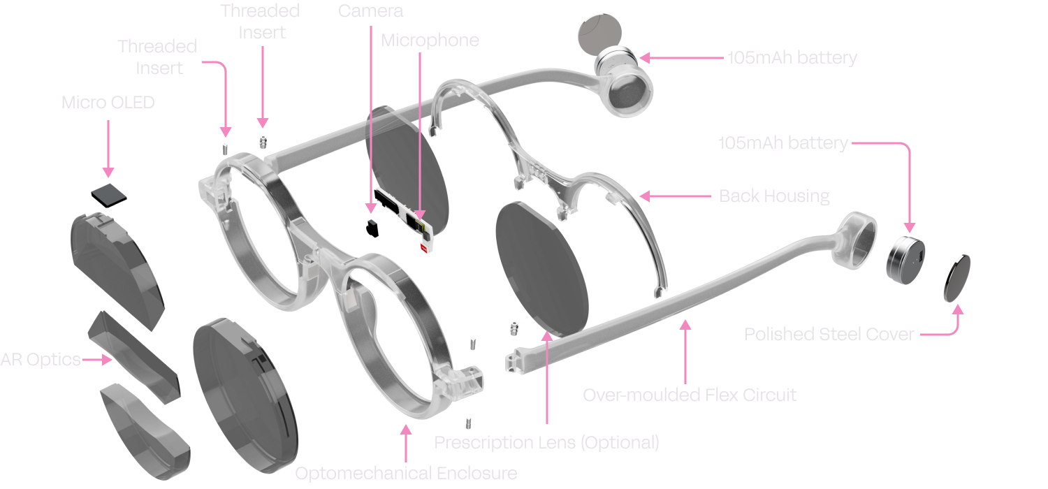
The display used in Frame is a 0.23” micro OLED. It features 640x400 RGB pixels and is optically bonded to the prism assembly which directs the image into the user’s eye. The result is a transparent floating display with a 20° field of view, and appears about the size of a tablet display at arms length.
The display is connected to the FPGA in 8bit YCbCr mode. 4 wires for the Y channel, and 2 wires each for the Cb and Cr channels. This allows for a total of 255 possible colors shown on the display. In turn, to save memory and ensure fast frame rates, the FPGA RTL is optimized to display a maximum of 16 colors per frame. These colors can be changed on the fly, allowing for large sprite sets and fonts to be efficiently stored within Frame’s embedded memory. To better understand how the graphics subsystem of Frame works, check out the graphics section of the Frame codebase repository.

Camera
The front facing camera sensor on Frame is the incredibly small and power efficient OV09734 from Omnivision.
The FPGA RTL optimizes images for AI applications such as image recognition and allows the user a large amount of control over resolution, gain and exposure for maximum flexibility.
Images are captured as 1280x720 RGB, but then cropped to 720x720 and converted to YCbCr for memory efficiency and fast downloading over Bluetooth. To better understand how the camera subsystem of Frame works, check out the camera section of the Frame codebase repository.
Microphone
Frame features a single ICS-41351 MEMS microphone from TDK. It has a wide dynamic range from -35.5dB to 129.5dB, allowing it to hear everything from soft speech, to loud booming noises.
The microphone is connected directly to the Bluetooth MCU which allows for low power operation and applications such as periodic recording and wake detection. The standard firmware allows for a wide range of recording formats from 4bits to 16bits sample depth, and 4kHz to 20kHz sample rate.
Motion Sensor (IMU)
The IMU on Frame is the 6 axis MC6470 sensor from MEMSIC. It features both an accelerometer and e-compass in a tiny package consuming very little power. Further processing on the Bluetooth MCU calculates the raw X, Y and Z values of both sensing elements into angular values for detecting head position.
An accelerator interrupt line from the IMU is also directly connected to the Bluetooth MCU. This allows for always on detections of taps that can be used to navigate and select UI elements within the user’s apps.
Power
Power is internally distributed within Frame via the MAX77654 power management IC from Analog Devices. Each rail is carefully managed and monitored to both protect the components within Frame, as well as ensure lasting performance of the battery.
The PMIC is configured from C code baked into the Bluetooth MCU firmware. If you’re creating a custom firmware, it’s recommended to avoid changing any of the PMIC settings without carefully studying the schematics and PMIC datasheet. These settings can easily over-volt components damaging them, as well as damage the battery.
Battery charging
The PMIC includes an integrated battery charger for the two built in 105mAh li-ion cells. Regulation is based on time, temperature and the current operating state of Frame. An analog pin provides the ability to monitor battery voltage and current within the firmware, and can be used to estimate battery life.
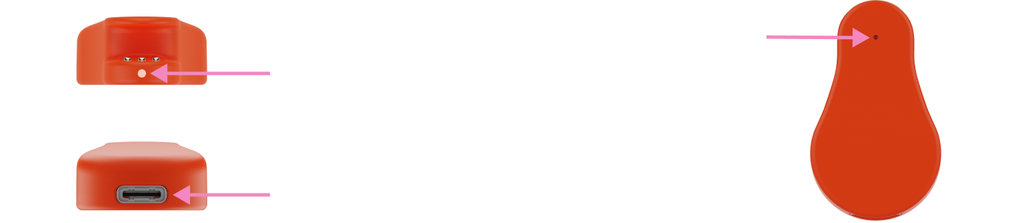
Charging cradle (Mister Power)
The charging cradle functions to both charge Frame via the 5V terminal on the back of the glasses, as well as allowing for factory resetting and un-pairing of Frame from any connected device.
It also contains a 140mAh rechargeable li-ion cell which allows for a top-up of Frame’s internal battery while on the go. The charging cradle itself, and in turn Frame, can be charged using any USB Type-C power supply.
Schematics
Frame
Charging cradle
Mechanical
Details coming soon
Frame
Download the 3D Model in STL format
Charging cradle
Download the 3D Model in STL format
Prescription (Rx) clip
Download the 3D Model in STL format
Device characteristics
Typical and absolute device characteristics are shown below. To get the best lifetime of Frame, it’s recommended to keep within these limits.
Typical characteristics
| Min | Typ | Max | |
|---|---|---|---|
| Frame operating current | 45mA | 80mA | 100mA |
| Frame sleep current | - | 580uA | - |
| Frame shutdown current | - | 132uA | - |
| Frame charging current | 1.5mA | - | 225mA |
| Charging cradle current | - | - | 400mA |
| Bluetooth radio power | -20dBm | - | 8dBm |
| Bluetooth sensitivity | - | - | -95dBm |
Maximum ratings
| Min | Typ | Max | |
|---|---|---|---|
| Frame charging voltage | -0.3V | 5.1V | 6.4V |
| Charging cradle USB voltage | -0.3V | 5.1V | 7V |
| Operating temperature | 0°C | - | 45°C |
| Storage temperature | -20°C | - | 60°C |
Safety & limitation of liability
Safety
Brilliant Labs’ devices can obscure your vision and should not be used while driving or operating dangerous equipment. Additionally long periods of use may cause eye strain, headaches and motion sickness. Brilliant Labs’ devices can also display bright flashing images so may not be suitable for those who are susceptible to light sensitivity.
Critical applications
Brilliant Labs’ devices are intended for consumer and R&D applications. It is not verified for use where performance and accuracy would be critical to human health, safety or mission critical use.
Lithium batteries
Lithium batteries can be dangerous if mishandled. Do not expose Brilliant Labs’ devices to excess temperatures, fire or liquids. Do not try to remove the battery as the terminals can become shorted and result in the battery overheating or catching fire. Once the product reaches the end of it’s life, dispose it safely according to your local regulations, such as e-waste collection points where any volatile components can be properly contained and handled.
FCC notice
This device complies with part 15 of the FCC Rules. Operation is subject to the following two conditions: (1) This device may not cause harmful interference, and (2) this device must accept any interference received, including interference that may cause undesired operation.
Any Changes or modifications not expressly approved by the party responsible for compliance could void the user’s authority to operate the equipment. Note: This equipment has been tested and found to comply with the limits for a Class B digital device, pursuant to part 15 of the FCC Rules. These limits are designed to provide reasonable protection against harmful interference in a residential installation. This equipment generates uses and can radiate radio frequency energy and, if not installed and used in accordance with the instructions, may cause harmful interference to radio communications. However, there is no guarantee that interference will not occur in a particular installation. If this equipment does cause harmful interference to radio or television reception, which can be determined by turning the equipment off and on, the user is encouraged to try to correct the interference by one or more of the following measures:
- Reorient or relocate the receiving antenna.
- Increase the separation between the equipment and receiver.
- Connect the equipment into an outlet on a circuit different from that to which the receiver is connected.
- Consult the dealer or an experienced radio/TV technician for help.
The device has been evaluated to meet general RF exposure requirement. The device can be used in portable exposure condition without restriction.
Limitation of liability
Brilliant Labs provides technical data, including design resources, examples, applications, design advice, tools, safety information and other resources “as is” and disclaims all warranties, express and implied, including without limitation any implied warranties or merchantability, fitness for a particular purpose or non-infringement of third party intellectual property rights.
These resources are intended for skilled developers. You are solely responsible for selecting the appropriate products for your application, designing, validating and testing your application, and ensuring your application meets applicable standards, and other safety, security, regulatory or other requirements.
Brilliant Labs reserves the right to change the circuitry and specifications without notice at any time. The parametric values quoted in this manual are provided for guidance only.
The resources and products are provided subject to our terms and conditions.