Monocle Hardware Manual
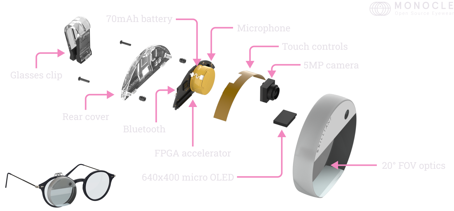
Monocle is a tiny heads-up display which clips onto your existing eye-wear. It’s packed full of powerful hardware which is perfect for when you’re on the go. It connects to your mobile phone over Bluetooth, and includes a few handy sensors such as touch buttons, camera and microphone. The included FPGA is perfect for computer vision, AI or graphics acceleration directly on the device. Monocle runs open source software and provides an easy way to get started using MicroPython. You can also write your own firmware from scratch using these docs as guidance.
Key features:
- 640x400 color OLED display
- 20° FOV optical body
- 5MP camera
- Microphone
- FPGA based acceleration for ML/CV
- Bluetooth 5.2
- 70mAh rechargeable Li-ion battery
- Touch buttons
- Full featured MicroPython based OS
- Charging case with USB & 450mAh battery
Example uses:
- Generative AI on the go
- ML based image augmentation
- Computer vision research
- QR code & barcode detection
- Heads up telemetry
- AR app & game design
Contents
- Block diagram
- Bluetooth MCU
- FPGA
- Memory
- Display
- Camera
- Touch interface
- Microphone
- Power
- Charging case
- Developing custom firmware
- Schematics
- Mechanical
- Device characteristics
- Safety & limitation of liability
Block diagram
This diagram shows a general overview of the Monocle architecture.

Bluetooth MCU
The Bluetooth MCU serves as the main processor for Monocle. It handles the majority of control over the device, and is used for networking and scripting. The MCU used is a Nordic nRF52832 with 512KB of Flash memory, and 64KB of RAM. It supports Bluetooth 5.2, up to 2Mb/s.
By default, the nRF comes preloaded with our MicroPython firmware, however you are able to deploy your own custom firmware if you wish to do so.
Updating firmware over-the-air
Over the air updates can be performed via Nordic’s nRFConnect software either on Desktop, or on Mobile (iOS/Android). nRFConnect requires a .zip DFU file to perform the update.
The latest MicroPython release for Monocle can be found on our GitHub releases page.
FPGA
The FPGA is used for graphics acceleration, as well as image processing of the 5MP camera. It’s perfect for computer vision and AI tasks which can make direct use of the camera and microphone as inputs. The FPGA IC used is a Gowin GW1N-LV9MG100C6/I5 from the Little Bee Family. It contains 7k LUTs, 468kb of block RAM, as well as 608kb of Flash memory. An additional 1 megabyte (8 megabits) SPI Flash IC is also included in Monocle, and either flash space may be used for booting up the FPGA, or storing user data. For further details, see the Package & Pinout Guide.
By default, the FPGA comes pre-loaded our Graphics & Camera Accelerator IP and can be accessed using MicroPython commands. Our IP is a perfect starting point if you wish to create your own FPGA application.
The latest release for the FPGA IP can be updated via the Micropython update.fpga() command. It is also checked periodically if you are using the Brilliant App
To save power, the FPGA can be shutdown along with the camera and display when not needed. See the power section for details.
Memory
Aside from the built-in memories of the Bluetooth MCU and the FPGA, Monocle contains three additional memory ICs. One for flash, and two for RAM. The RAM is accessible by the FPGA, and is great for storing display buffers, camera data, or working data for AI algorithms. The flash meanwhile, is great as a secondary source for loading FPGA bitstreams, logging data, and is accessible by both the Bluetooth MCU and FPGA.
Flash
The Flash IC used is the Winbond W25Q80EWUXIE. It’s an 1 megabyte (8 megabits) serial Flash and is connected to the FPGA and nRF52 via an SPI bus.
RAM
The RAM ICs used are the AP Memory APS256XXN. A total of 64 megabytes (512 megabits) of memory is addressable, and can be accessed at up to 800Mb/s in DDR mode.
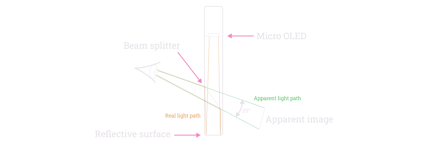
Display
The display used in Monocle is a 0.23” micro OLED. It features 640x400 RGB pixels, and is optically bonded to the main housing which directs the image into the users eye. The result is a transparent floating display with a 20° field of view. About the size of a tablet display at arms length.
To save power, the display can be shutdown along with the camera and fpga when not needed. See the power section for details.
Camera
The front facing camera on Monocle is an Omnivision OV5640. It is a 5MP color sensor and features numerous convince features such as automatic exposure control, and automatic white balance. It is connected directly to the FPGA over a high speed MIPI CSI-2 interface.

To save power, the camera can be shutdown along with the fpga and display when not needed. See the power section for details.
Touch interface
Monocle features two capacitive touch buttons which are fed into an Azoteq IQS620A touch controller. Each button can detect close proximity as well as touch events. With further software processing, double taps, long presses and other gestures can be detected. The touch controller is connected to the Blueooth MCU via I2C and an interrupt line to flag pending touch events. Our MicroPython firmware contains a built in library to access various types of touch events, and trigger actions when pressed.

Microphone
A TDK/InvenSense ICS-41351 microphone is directly connected to the FPGA, and can be used to record audio, or for voice recognition algorithms.
The audio port is located on the back side of Monocle, so is perfect for receiving the wearers voice, while avoiding excessive background sounds.

The microphone is connected via a PDM interface, and is on the same power domain as the FPGA.
Power
Monocle operates on the four power domains as shown below. The colored domains may be powered down by command of the Bluetooth MCU. If the FPGA is shutdown, all the connected peripherals including the display and camera will shutdown also.
Alternatively, the analog supplies of the camera (2.7V) and display (10V) may be powered down independently of the FPGA. This method, while not being the most aggressive power saving method, allows for faster startup of the camera or display as the digital registers do not need to be reconfigured.

Regulation
The Maxim MAX77654 PMIC is an efficient and low power management controller. Each rail is configurable and can be tuned for efficiency, stability or noise performance. Each rail can additionally be current limited to avoid overloading the battery.
The PMIC communicates solely with the Bluetooth MCU over I2C.
It’s possible to damage the Monocle hardware by setting the voltages levels too high. We recommend that you avoid diverging from the settings found in the Brilliant provided firmware, to prevent damaging your Monocle.
Battery charging
The PMIC also includes an integrated battery charger. Charge regulation voltage and current can be configured, as well as various timings. The battery level, and charge current can also be read via an analog pin provided from the PMIC to the Bluetooth MCU.
It’s possible to damage the Monocle battery by misconfiguring the charge voltage or current. We recommend that you avoid diverging from the settings found in the Brilliant provided firmware and to prevent fire or damage to the Monocle battery.
LEDs
Monocle contains two LEDs (green and red) connected to GPIOs on the PMIC. They are easily accesible via PMIC registers from the Bluetooth MCU.

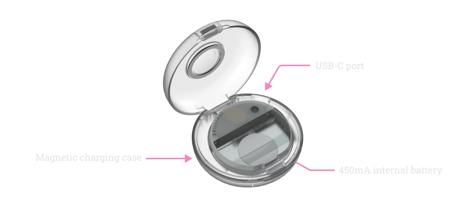
Charging case
Monocle is provided with a compact charging case for taking on the go. When inserted into the case, Monocle will begin to recharge from the charging case battery. The case battery can provide several full charges of the Monocle and be itself recharged from a standard 500mA USB Type-C jack. While charging, the case will show an orange LED. Once the LED turns off, the case is fully charged.
When placed into the charger, the Monocle will detect the charge voltage and shut down all peripherals to efficiently charge. Upon removal from the case, and touching of either of the touch pads, Monocle will return into its normally powered state.
Note that once placed into the charging case, it can take up to 10s for charging to begin. During this time, Monocle will look as if it’s awake. If Monocle does not go to sleep after 10 seconds, ensure that the charging case is sufficently charged (by placing it on USB-C charging), or ensure that device.prevent_sleep() is disabled.
Developing custom firmware
Developing for the Bluetooth MCU
It’s possible to damage the Monocle hardware by misconfiguring the power supply controller. We recommend that you avoid changing any of those settings as we’ve already fine tuned them for you.
A good place to start writing your custom nRF applications is the Monocle MicroPython repository. All the hardware drivers can be found here and you can follow the main() flow to understand how Monocle is booted.
For compiling projects, you will need to download the latest ARM GCC compiler. For Bluetooth connectivity, you will also need to download a compatible Bluetooth stack from Nordic (aka the Softdevice). This is a proprietary library from Nordic, so is not directly included within the Monocle MicroPython repository, however is free to download and use.
Creating custom OTA (over-the-air) update packages
It’s recommended that your application is well tested and can reliably return back into OTA mode after programming. If you flash a bad application, you’ll have to dismantle your Monocle and manually reprogram it using a programmer.
To generate the .zip file, you’ll need to use the nRF Util command line application. You can read how to generate files here. You will need to use the Brilliant OTA key in order to generate a compatible image. If you wish to change this key, you can create a new keypair, and add the public key within your bootloader code. Subsequent updates will then require your new private key. Note: without the key, it’s not possible to do over-the-air updates, and you will need to revert to manual programming.
Developing for the FPGA
GoWin’s EDA can be used to develop applications for the FPGA. You can request a free licence here.
We recommend having a look at our Graphics & Camera Accelerator IP to see how an FPGA project is set up and built.
Generally it’s convenient to use the MicroPython FPGA module to wirelessly program the FPGA. However this method does not allow for JTAG debugging, and can be a slow process for iterative development. It’s therefore also possible to program the FPGA manually using a programmer.
Note: Be sure to check your chip revision prior to developing and programming your application.
Manually programming
The internal hardware of the Monocle is very delicate, especially the OLED flex cable. This cable contains thirty tiny wires which can be easily be broken if the cable is creased. Additionally, the OLED is bonded to the optical prism for a clear picture. It’s impossible to replace this OLED if it breaks.
To access the programming pads, you’ll first need to remove the back cover.
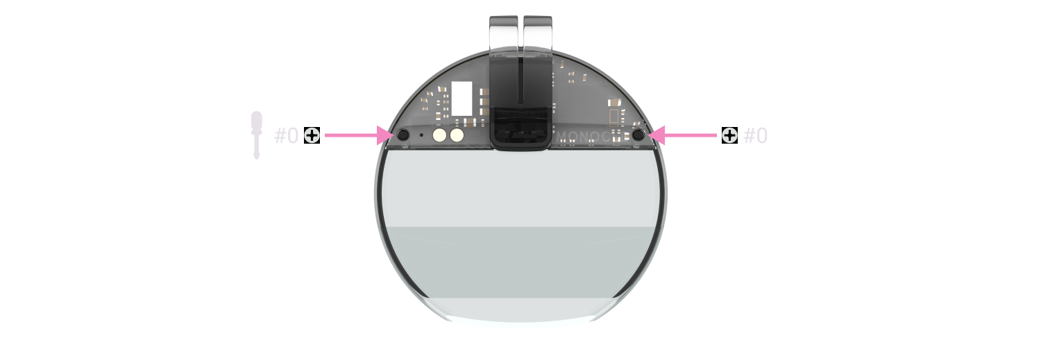
With the back cover removed, gently extract the main board, taking care not to damage the flex cables, or shorting any of the electronics.
To shutdown the power, you will need to short the two pads shown below. Metal tweezers work well, but be careful not to short any other components.
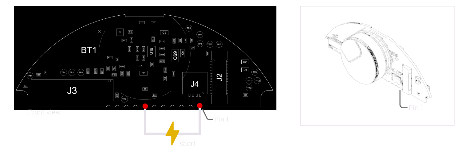
Your device should now be off, but note the battery pins will still be live. If you remove any components, take note of which way they were inserted into the connectors. Re-inserting the OLED cable or the camera module backwards will permanently damage them.
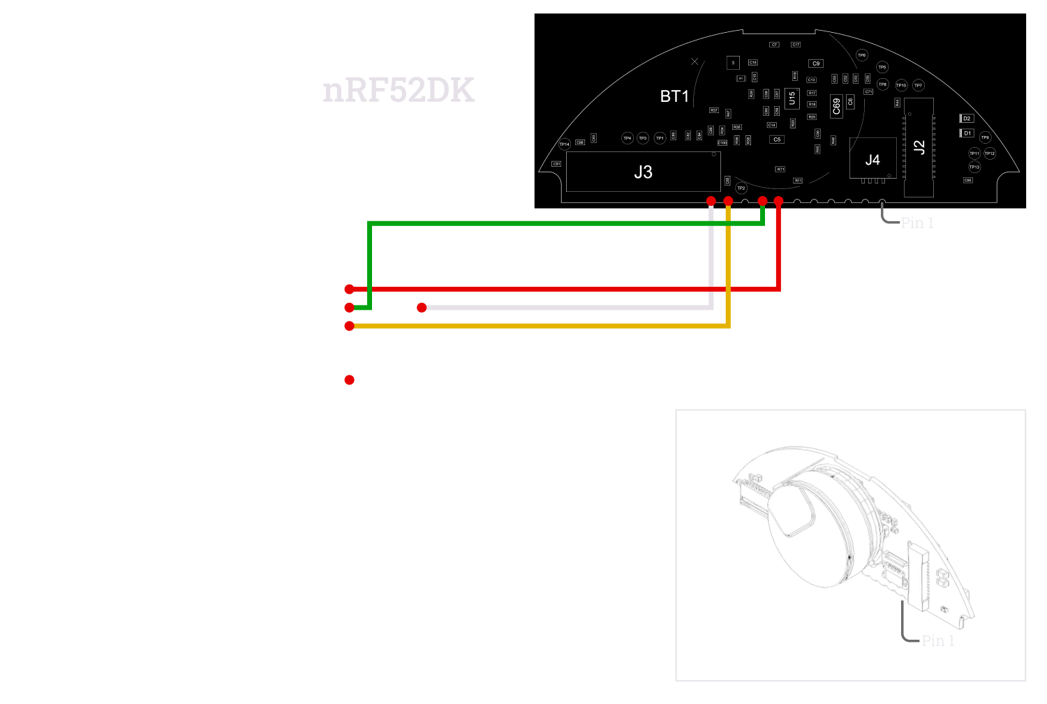
The programming pins for the Bluetooth MCU are shown below. It’s recommended to use a J-Link compatible programmer such as the nRF52 DK. Nordic provide a helper utility which is correctly aware of important settings and flags when reprogramming. However other OpenOCD based SWD programmers may work with some careful tweaking.
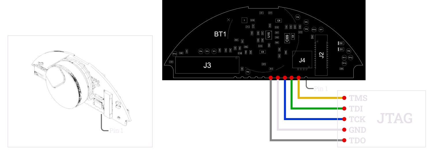
The programming pins for the FPGA are shown below. You can use Gowin’s GWU2X based dongles to program the FPGA directly from within the IDE. Alternatively, openFPGAloader works as an open source alternative and can be used with a variety of programmers, such as FTDI FT2232 based dongles. Note that you will need to perform level shifting between the 3.3V of most tools and the 1.8V of the FPGA, to avoid damaging it. If programming the internal flash, care must be taken to not perform so while the firmware is starting, which could provoke damage to the internal flash (see RECONFIG_N).
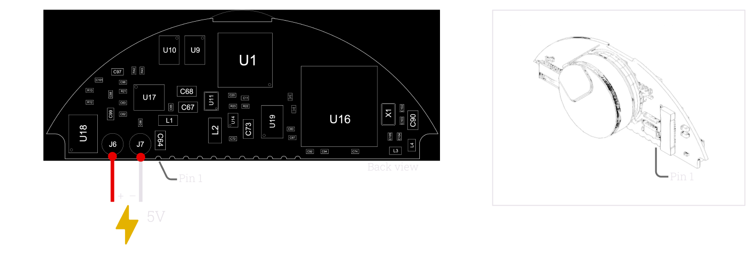
To power the device, apply 5V to the charging pads.
To program the Bluetooth MCU, install the Nordic command line tools, and then run the command:
nrfjprog --program firmware.hex --chiperase -f nrf52 --verify -rTo program the FPGA with openFPGAloader, run the command:
openFPGALoader --cable ft2232 --fpga-part 0x0100481b --write-flash bitstream.fs
Schematics
Download the PDF schematics for Monocle here
Download the PDF schematics for the Monocle charging case here
Mechanical
Monocle
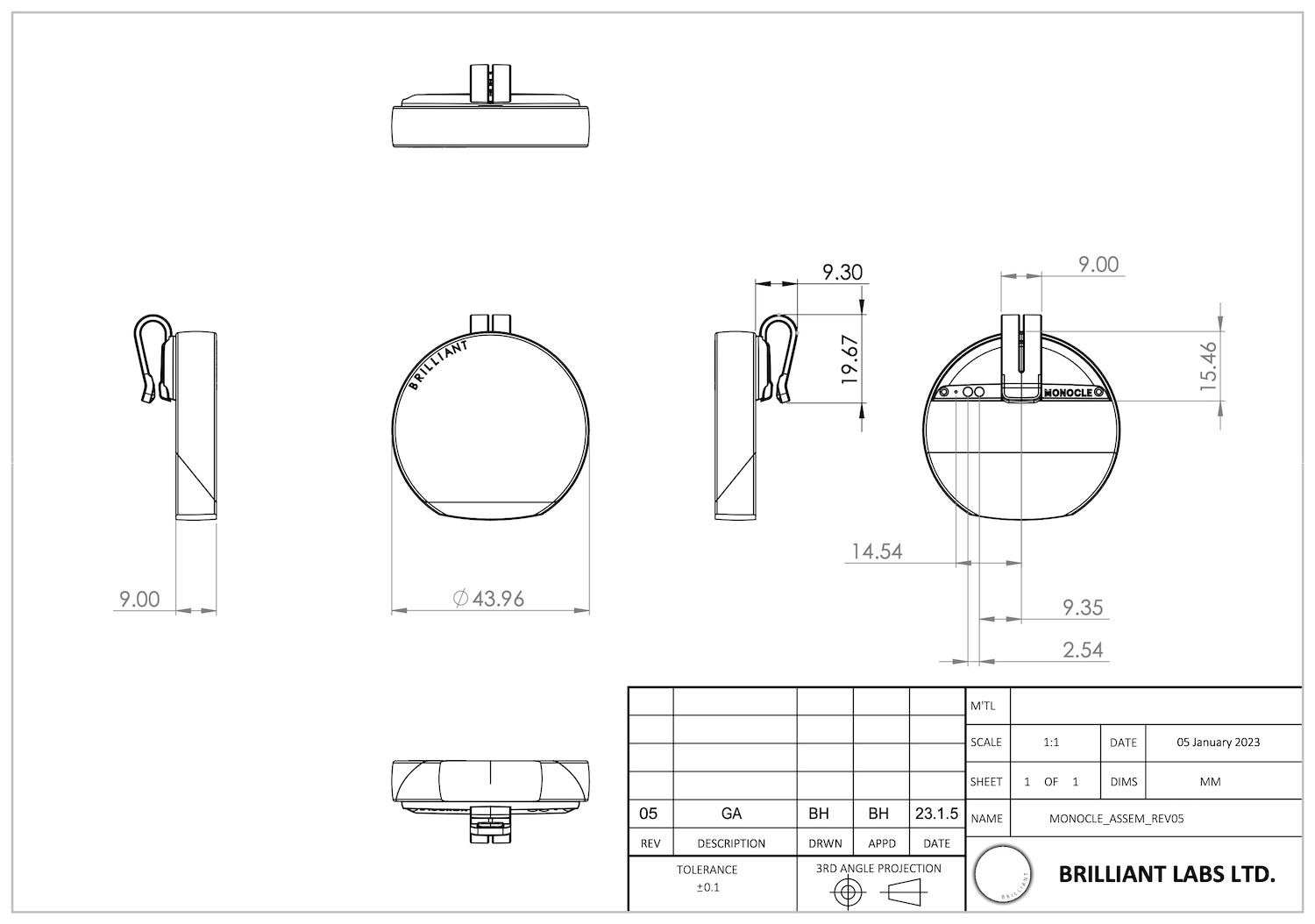
Download the 3D Model in STEP format
Download the 3D Model in STL format
Charging case
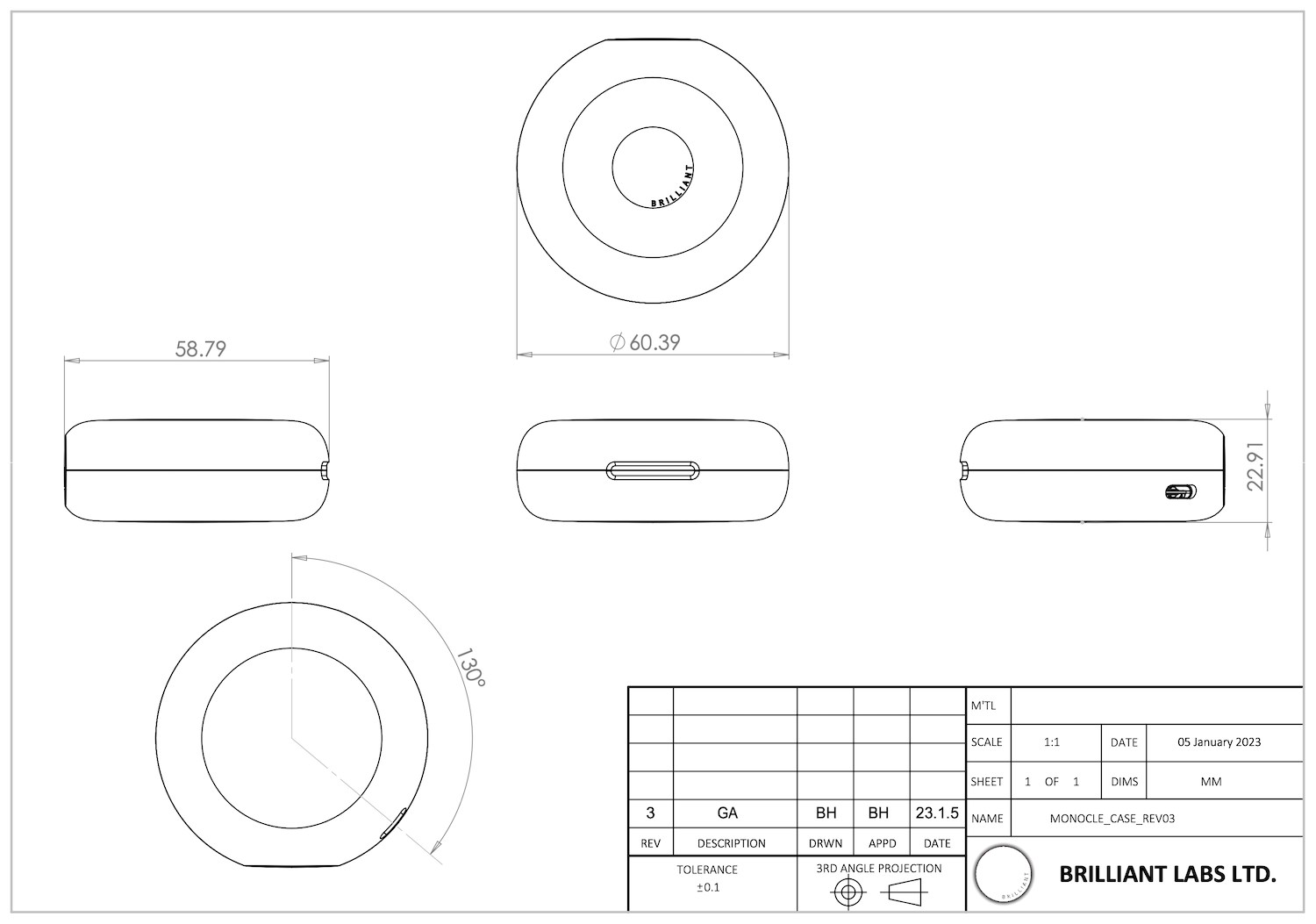
Device characteristics
Typical and absolute device characteristics are shown below. To get the best lifetime of your Monocle, it’s recommended to keep within these limits.
Typical characteristics
| Min | Typ | Max | |
|---|---|---|---|
| Monocle charging current | - | - | 77mA |
| Case USB charging current | - | - | 500mA |
| Bluetooth radio power | -20dBm | - | 4dBm |
| Bluetooth sensitivity | -96dBm | - | - |
Maximum ratings
| Min | Typ | Max | |
|---|---|---|---|
| Case USB charging voltage | -0.3V | 5.1V | 30V |
| Monocle charging voltage | -0.3V | 5.1V | 28V |
| Operating temperature | 0°C | - | 45°C |
| Storage temperature | -20°C | - | 60°C |
Safety & limitation of liability
Safety
Brilliant Labs’ devices can obscure your vision and should not be used while driving or operating dangerous equipment. Additionally long periods of use may cause eye strain, headaches and motion sickness. Brilliant Labs’ devices can also display bright flashing images so may not be suitable for those who are susceptible to light sensitivity.
Critical applications
Brilliant Labs’ devices are intended for consumer and R&D applications. It is not verified for use where performance and accuracy would be critical to human health, safety or mission critical use.
Lithium batteries
Lithium batteries can be dangerous if mishandled. Do not expose Brilliant Labs’ devices to excess temperatures, fire or liquids. Do not try to remove the battery as the terminals can become shorted and result in the battery overheating or catching fire. Once the product reaches the end of it’s life, dispose it safely according to your local regulations, such as e-waste collection points where any volatile components can be properly contained and handled.
Limitation of liability
Brilliant Labs provides technical data, including design resources, examples, applications, design advice, tools, safety information and other resources “as is” and disclaims all warranties, express and implied, including without limitation any implied warranties or merchantability, fitness for a particular purpose or non-infringement of third party intellectual property rights.
These resources are intended for skilled developers. You are solely responsible for selecting the appropriate products for your application, designing, validating and testing your application, and ensuring your application meets applicable standards, and other safety, security, regulatory or other requirements.
Brilliant Labs reserves the right to change the circuitry and specifications without notice at any time. The parametric values quoted in this manual are provided for guidance only.
The resources and products are provided subject to our terms and conditions.